 |
UNA CSIS |
 |
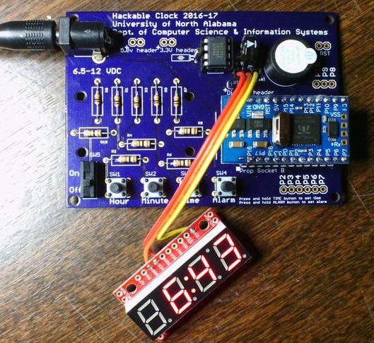
The University of North Alabama student chapter of ACM co-sponsored the Hackable Clock Project with the Department of Computer Science and Information Systems. Participants in the extracurricular project received a kit containing all of the electronic components, printed circuit board (pcb), and software tools to assemble and program their own digital alarm clock.

Completed clock (revision A)
The clock is based on the Parallax Propeller chip and the software is written in C. The clock was designed by Dr. Jerkins and was conceived to be “hackable”. The pcb has two design features that make it hackable. First, the clock's functionality may be extended using the exposed CPU pins (P2-P10) along with 3.3V and 5V power connectors designed into the pcb for enhancing the clock's capabilities (for example: obtain time from GPS, control the clock with a phone app, connect the clock to wireless). Second, the CPU board (processor, memory, power) is connected to the clock pcb via standard 0.1" male headers socketed into female headers. This design feature means the processor module can be popped off and inserted into a breadboard for prototyping. These two features (exposed pins and power, and a removable processor module) permit the participants to hack on hardware and experiment with microcontroller programming.
The clock kit is also designed to be easy to assemble. All of the components are through-hole (PTH) soldered. The spacing between components is large enough so that beginners can quickly learn how to be successful soldering. The tools needed to assemble the clock are an inexpensive soldering iron, solder, safety glasses, brass sponge, and a vise or “helping hands” type tool. A solder vacuum or solder wick is also handy to fix any bridged connections.
The basic clock allows the user to set the time (hour and minutes), set an alarm (hour and minutes), and turn on and off the alarm. The time and alarm functions are manipulated using the buttons and switch along the bottom of the pcb. The clock is powered by a 7.5VDC wall wart and the design includes a super capacitor to maintain the clock configuration during power outages. No enclosure was provided in the kit allowing each participant to create their own (see below for Dr. Jerkins' version).
Participants met semi-monthly throughout the 2016-17 academic year to assemble their clocks (solder components together) and develop the software. Design guidance for the software was provided by Computer Science faculty Dr. Jerkins and Dr. Terwilliger. This web page documents the kit components, data sheets, and software tools for the project. If you or your organization are interested in the Hackable Clock Project, you may contact UNA ACM via Dr. Jerkins (use email, no phone calls please).
Printed Circuit Board (pcb)

Front of pcb (revision A)

Back of pcb (revision A)
Component datasheets & Schematics
- Microcontroller datasheet
- Microcontroller, memory, and power supply board schematic
- Speaker
- Timekeeping IC (RTC)
- Oscillator (crystal)
- Super capacitor
- SPST push button
- SPDT switch
- Serial 7 segment LED display
- Barrel jack
- PCB schematic
Software Design
- High level flowchart for software
- Bit banging (Wikipedia)
- Bitwise manipulation (Wikipedia)
Software Tools
Important: Carefully read the instructions for installing and configuring the software on the linked pages.- SimpleIDE software, Propeller C compiler and IDE
- Windows 10 serial driver, Install this first for Windows 10 SimpleIDE
- Learn Library Folder, Update to the latest libraries after installing SimpleIDE
- Propeller C tutorials (Parallax)
Soldering Tutorials
Bill of Materials
| Item | Description |
|---|---|
| CPU, power, memory | Propeller mini |
| Programmer | Prop plug with USB cable |
| Speaker | Piezo, square wave 5 Vp-p |
| Power supply | 7.5 VDC wall wart |
| Timekeeping IC | Dallas DS1302+ RTC |
| Oscillator | 32.768 KHz, 6 pF, axial crystal |
| RTC power backup | 0.22F Super capacitor, 5.5V, SD |
| Push buttons | SPST tactile switch, 6mm, (4) |
| Pin headers | Male header, 0.1" spacing, 2x12 pins, 1x6 pins, 2x3 pins, 2x2 pins |
| Pin headers | Female header, 0.1" spacing, 2x12 pins |
| Resistor | 100 Ohm, 1/4 watt, (5) |
| Resistor | 10K Ohm, 1/4 watt, (5) |
| Alarm on/off switch | SPDT mini power switch, 30V, 200ma, (1) |
| LED display | 4 digit, 7 segment LED display (serial, SPI, i2c) |
| Main board to LED jumper | 3 wire jumper, 12" (cut in half) |
| DIP socket | 300 mil, 8 pin, solder tails |
| Power connector | Barrel jack, center pin pos |
| Printed circuit board | Custom designed pcb, 2.5" X 3.5" |
| Kit container | Reclosable anti-static bag, 6" X 10" |
| Kit container label | Printed adhesive label, 1" X 4" |
Enclosure / Stand
An enclosure was not included as part of the project.
Dr. Jerkins designed this simple mount/stand for his clock and had it cut from 1/8" clear acrylic on a laser cutter. Each image represents a 5" X 5" sheet of acrylic where the lines are cuts and the text is etched. This design works as either a desktop stand with two angled feet so the clock is tilted back or as a hanging wall mount. When used a stand, one of the wall mount tabs can be used as cable management for the power cord.

Template for clock mount/stand - sheet 1

Template for clock mount/stand - sheet 2

|

|

|

|